|
Short description |
|
The hardware consists of power-supply unit, microcontroller unit, LCD display, 4 buttons, 3 LANC connectors (1 LANC connector for optional external remote controller), power-supply socket and switches. |
|
|
|
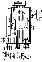
Electronic scheme |
|
Version 0.3 (in gif and eps format and in zipped PCad format) Changes from the previous version:
Older versions:
Version 0.2 (in wmf and eps format)
|
|
|
|
Case |
|
Dimensions of the case:
120x59x36mm; Conrad electronics No. 522120. Description (pdf file with measures). |
|
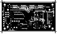
PCB layout |
|
Version 0.3 PCB layouts and electronic layouts in Pcad format (zipped pcb) Top-side printed circuit board (in gif and eps format) and bottom-side printed circuit board (in gif and eps format) |
|
|
|
Electronic layout |
|
Version 0.3 PCB layouts and electronic layouts in Pcad format (zipped pcb) Layout of electronic elements - top side (in gif and eps format), and bottom side (in gif and eps format) |
|
|
|
Bill of materials |
| List of used electronic components and connections. |
|
|
|
Important note |
| Do not replace 74LS05 with 74HCT05! |
Connections

