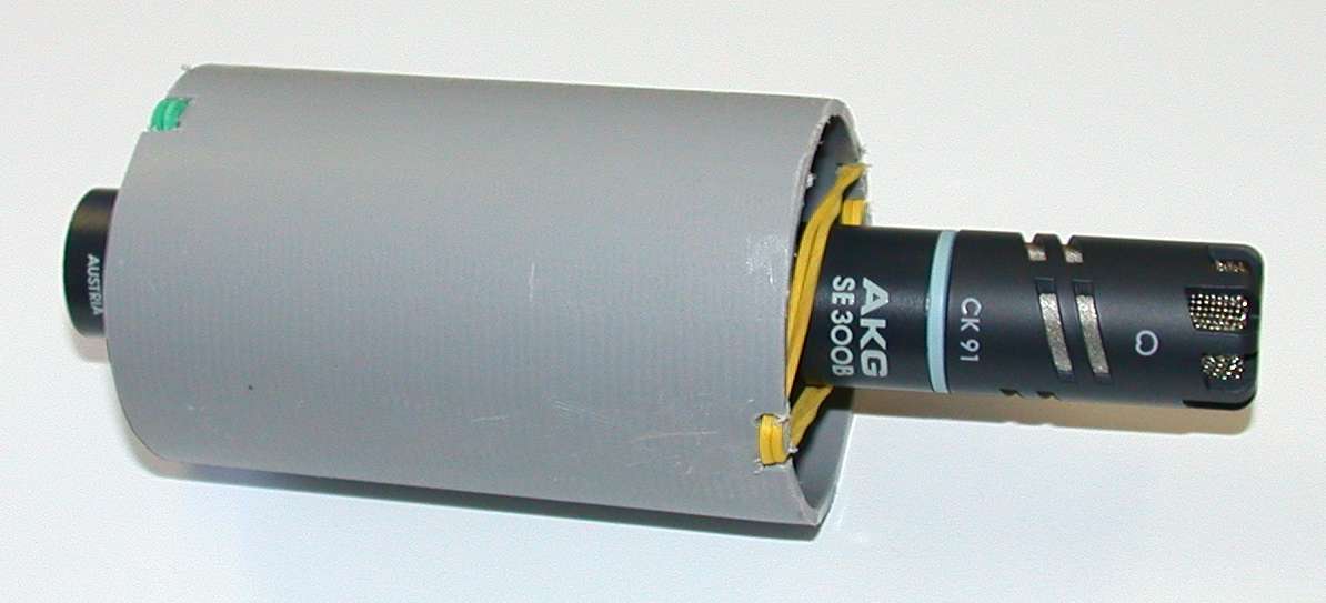
 Click
on the picture to get enlarged view!
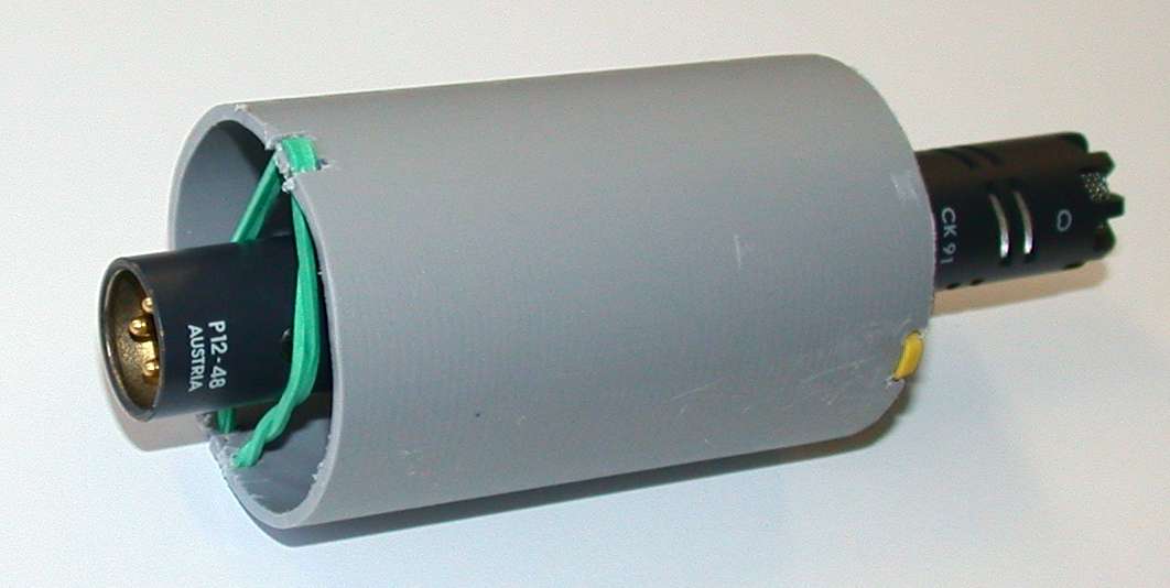
Click
on the picture to get enlarged view!Just
for testing purposes I have made
So, shockmounts might be quite useful when mounting microphones on camcorder's hotshoe (nothing new, isn't it?).
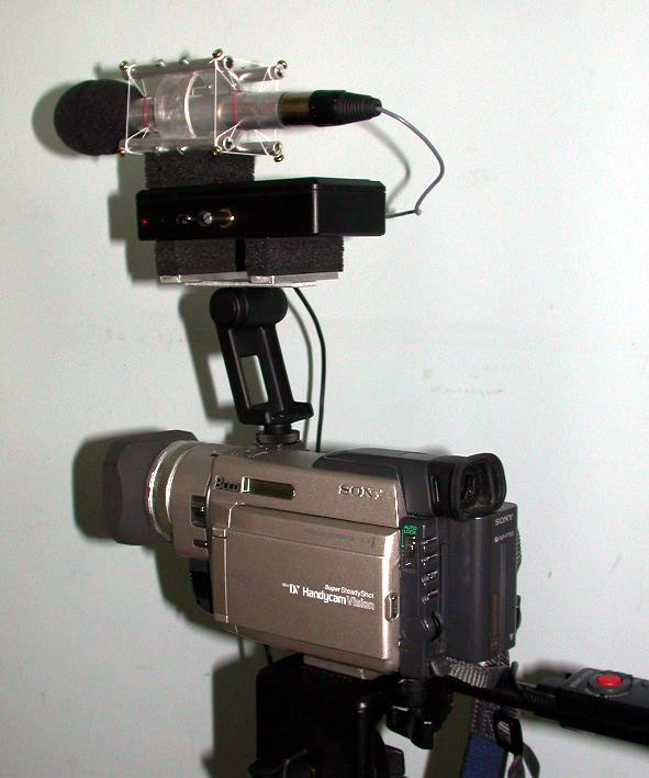
The final version is now quite modified (due to several reasons :-):
Click
on the picture to get enlarged view!
I have tested the above "construction" one evening (near my house) and I've got the following result (mainly faint sound "produced by" crickets, some cars quite far away (more than 3km or 2 miles), and somebody using a hammer? at 9PM). The additional amplification of the mike was 15dB (mike capsule is AKG CK91, all the electronics home made) and connected to the modified mike input of TRV 900. Inside my house, if there are no additional noises present, I can hear relatively faint noise produced by the TRV900E, especially when the mike is close to walls (TRV900 noise is reflected from the wall). I played one song on my "not so perfect" Hi-Fi (see details). Mike (on the "shockmount") has been placed about 40cm from a loudspeaker. The comparison between the original song from a CD, TRV900 internal mike, and the external mike (once by using auto gain and by using the "manual gain" with modified audio path) is given in the following table*:
*Note that faint additional broom, produced by the amplifier, can be heard in silent parts. For fair comparison only the left channel sound is given.
**The signal has been distorted even though 0dB external amplification has been used.
An electronic scheme of a mike amplifier (within mike body) is given here (R1 should be 2K and R7 should be 10K, the scheme with element C7 is still not tested), and a scheme of an attenuator (the black box above the TRV900 and below the mike) is given here. The block scheme of the whole system is given here.
PCB layouts are below:
device |
component layout |
PCB-bottom side |
PCB-upper side |
mike amplifier |
|||
attenuator |
When I find more time, I'll give specifications and explain the circuits and construction in more details (meanwhile you can contact me on my e-mail: damir.vrancic@ijs.si).